EMIStream
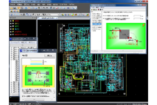
EMI Design Rule Check
EMIStream is an EMI Design Rule Check and Power/Ground Resonance Analysis tool that can suppress undesirable EMI generated from PCB at an early design stage.
EMIStream is based on experience of EMC export engineers worldwide seeking solutions
for their real world EMI problems, As a member of a prestigious US based EMC consortium, NEC continues its research and development to enhance EMIStream.
By using EMIStream to eliminate possible EMI issues at the PCB design stage, you will be
able to save time that would otherwise be spent on complex fixes for EMI problems.
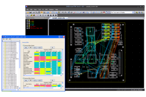
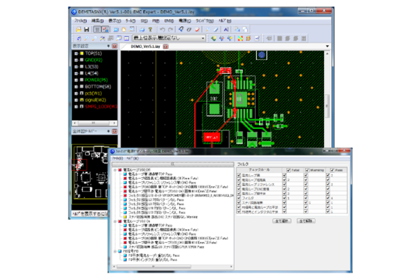
Check Items (15 rules)
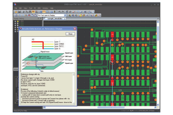
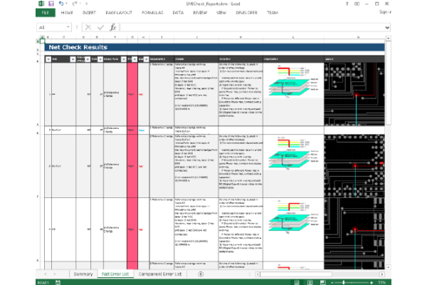
Return Current Path Discontinuity Check
- 1.Reference Change
- 2.Return Current Path Discontinuity
- 3.Traces Near Plane Edge
- 4.SG Trace
- 5.SG Via Spacing
Power Plane Check
- 1.Grounding Vias Along Plane Outline
- 2.Decoupling Capacitor
- 3.Digital/Analog Interference Check
- 4.IC Ground Split Check
Trace Check
- 1.Trace Length
- 2.Via Count
- 3.Estimated Radiation
- 4.Filter
- 5.Differential Signal
- 6.XTalk
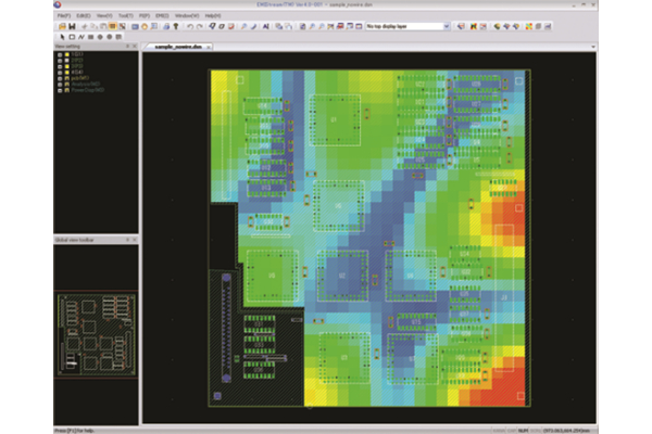
Power/ Ground Resonance Analysis
EMI increases if resonance occurs between the power/ground.
The Power/ Ground Resonance Analysis Function takes into account plane shapes, capacitors, and distance between the power/ground planes to analyze resonance based on the PEEC (Partial
Element Equivalent Circuit) method.
ESD Rule Check ( Option )
A discharge can occur when an electrically charged object (including the human body) touches an electronic device. This phenomenon called ESD (Electrostatic discharge) causes malfunction and failure of electronic devices.
EMIStream ESD Rule Check Feature will detect areas where ESD tolerance levels are low on a PCB and offer suggestions for solutions.
Check Items (10 rules)
Signal Trace Check Group
- 1.Traces Near Plane Edge
- 2.Traces crossing over power and ground plane
- 3.Signal trace over the slit of the ground/power plane
- 4.SG Trace
- 5.SG Via Spacing
- 6.Power Protection
Component Placement Validity Check Group
- 1.Input Pin Protection
- 2.Power Pin Protection
- 3.Reset Line Protection
FG Pattern Check Group
- 1.FG Pattern
SMPS Rule Check ( Option )
The application of switched-mode power supply (SMPS) is expanding in
line with the pursuit of power saving performance and smaller size of products.
Spike noise is generated (LC resonance) and leaks by loop current.
The layout needs to be designed to minimize the leak of loop current and spike noise.
Check Items (9 rules)
Current Loop
- 1.Current Loop Layer
- 2.Current Loop Length
Prevention of noise leak
- 1.Current Loop Reference
- 2.Current Loop Ground Area
- 3.Current Loop Interference
- 4.Filter
Snubber circuit
- 1.Snubber Circuit Placement
Feedback
- 1.Feedback and Current Loop Interference
- 2.Feedback and Inductor Interference