PLATO
INTRODUCTIONS
The 5th Generation 3GPP wireless communications standard, also known as 5G, will soon become available to the public. Compared to the 4th Generation 4G wireless services, 5G will offer improvements in communications speed, reduced latency and increased capacity. Two key enabling factors of 5G are its adoption of millimeter wave frequencies and utilization of directional phased array antennas.
There is growing concern that the millimeter wave electromagnetic fields (EMF) radiated by 5G devices may have harmful effects, especially when concentrated or focused by phased array antennas. At lower 4G frequency bands (<10GHz) Specific Absorption Rate (SAR) measurement techniques were traditionally used to assess the potentially harmful effects of human exposure to wireless signals. SAR techniques are not sufficient, however, to assess applications above 10GHz because skin surface heating is dominant at frequencies above 10GHz. This requires higher frequency EMF exposure techniques and standards to be adopted to address 5G millimeter wave device EMF exposure.
For 5G applications, Power Density measurement techniques are being adopted to assess the safety of wireless signal levels for applications greater than 10GHz and to ensure conformance to EMF exposure limits. The Plato platform offered by Microwave Factory is a turn key Power Density measurement system for evaluating EMF exposure at 5G millimeter wave bands.

SOFTWARE
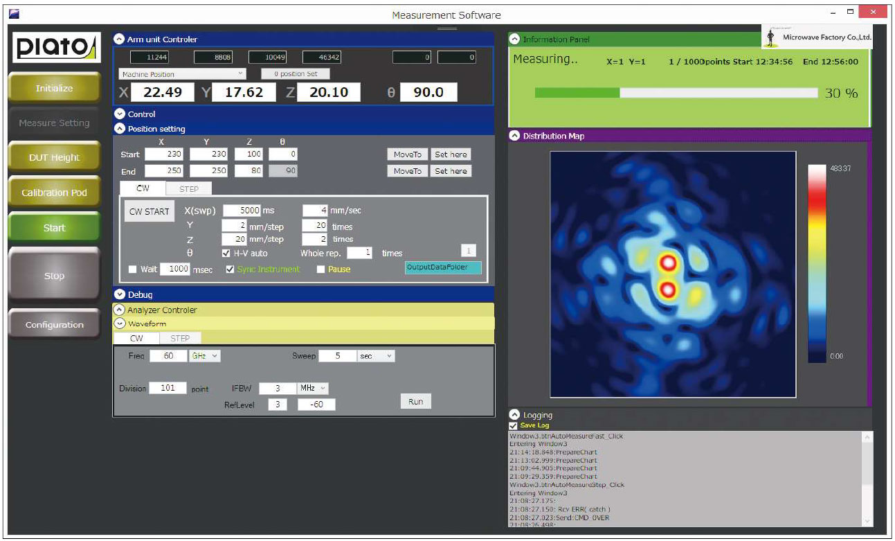
Plato is designed and developed a power density measurement system. This system is used for evaluation of the power density at millimeter wave frequency for wireless devise. Thus, Plato is able to confirm compliance to RF-EMC exposure standards for wireless devices using this system.
Plato software automatically calculates and displays power density values according to a reconstruction algorithm based on data acquired from the instrument. The user determines the range of measurement and the Plato software automatically measures the maximum power density.
RECONSTRUCTION ALGORITHM
There are several method to evaluate power density of wireless devices. One of the evaluation method is based upon the evaluation Electric Filed (E-field) and Magnetic Field (H-field). Another method is based on plane wave equivalent approximation. For power density based on E- and H- fields, the near E- and near H-fields are measured on a surface and the their Poyinting vector evaluated. Fig.1 shows schematic view of power density assessment in close proximity to a device using this technique.
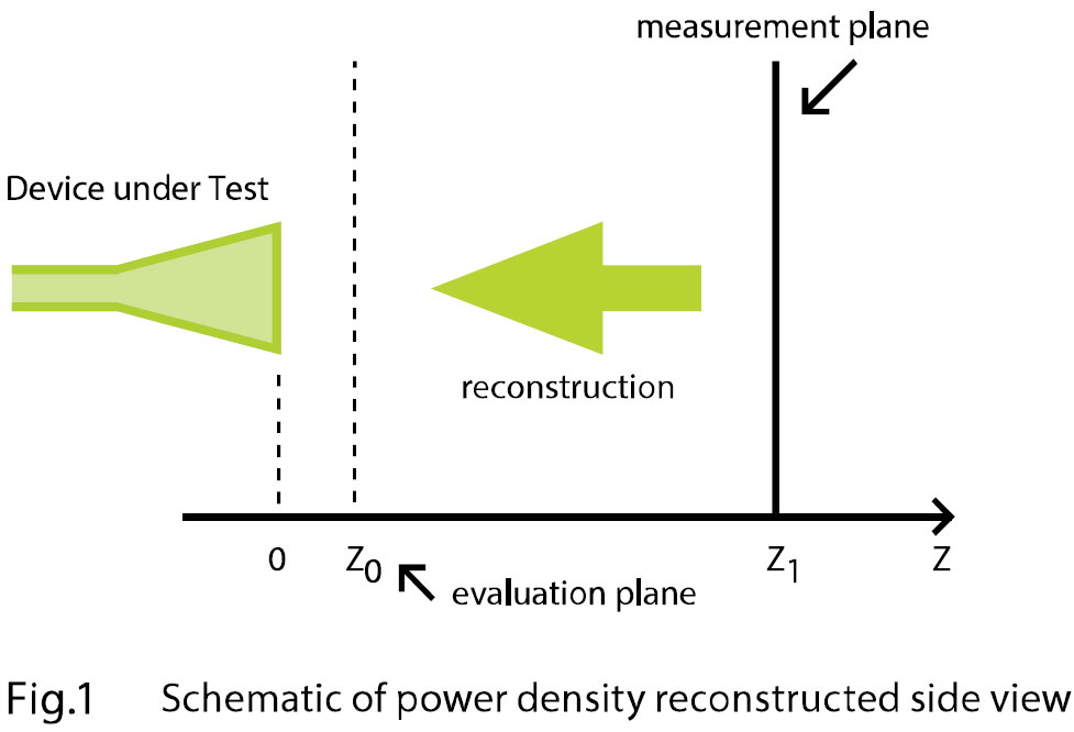
- Measure Ex and Ey Fields on Measurement Plane z1
- E-fields on the evaluation plane z0 are reconstructed
- H-fields on the evaluation plane z0 derived using reconstructed E-fields
- Power density evaluated from E and H fields at evaluation plane zo
- Extended capability of Phaseless Measurements for power density evaluation
SPECIFICATIONS IN BRIEF
| SHIELDED CHAMBER | Frequency range | 18GHz to 50GHz | |
|---|---|---|---|
| Shielding effectiveness | 18GHz to 50GHz | > 70dB | |
| Dimensions (W * H * D) | outside dimensions and chamber mount | 1.2m * 1.2m * 2m | |
| Axis | 6 | ||
| Weight | with Scanner and chamber mount | < 450kg | |
| Door operation | manually operated | ||
| SCANNER SYSTEM | Angular resolution | VH switching | 0.02˚ |
| Positioning repeatability | azimuth/elevation | 0.01mm | |
| Load capability | weight | 3kg | |
| maximum dimensions of the DUT | 20cm * 20cm | ||
| MEASUREMENT ANTENNA | Probeantenna | ||
| Frequency range | 26.5 GHz to 40 GHz | Option > 40GHz | |
| OPTION | Probe antenna | Waveguide port antenna for each band | |
| Accessory | ATT, Amp, mixer, source module, RF cable | ||
| PC | software | include PC |
Near Field measurement system @ PLATO
MWF could achieve the measurement system of mm-wave devices by Near-Field, not Far-Field, which enables the customer to measure in the compact space.
The advantage of Near-Field measurement ;
Usually, Antenna measurement system is under Far-Field solution, which takes enough distance to DUT position. Thus, it demands the enough space of chamber rooms due to Antenna size is bigger than wavelength though DUT of mm-wave itself is small.
However, Near Field measurement is much compacted as mentioned.
How to achieve??
IEEE have announced the procedure to convert the Near-Field to Far-Field antenna measurement data by using Fourier Transforming. In additional with this conversion processing, we, MWF, have already PLATO, which is Power Density measurement system for 5G devices and enable to measure the Planer on the surface of devices, so we could build the Near Field measurement system by combined those solution.
Antenna of mm-wave devices and Reason for requirement of wide space to measure
In case of mm-wave application, the shape of antenna is much different with UHF & VHF band, then Plane antenna or Phased-Array Antenna with directivity would be popular. The border line between Near-Field and Far-Field is formulated as 2D^2/λ(λ : wavelength, D : Max Dimension of antenna) in general, so the border line is more far from antenna position with inverse proportion of wavelength (meaning high frequency). Then, the measurement system for mm-wave would be bigger.
However, our PLATO solution could resolve the issues as above and is suitable for such antennas NF conversion procedure.
Electromagnetic Field Simulation (Feko) vs PNF (Planer Near Far) conversion Comparison data shown in Fig.1
The measurement range is limited from +90deg to -90deg, and it is not so good accuracy on the edge field(closeto90deg), however most of the others is so match between them. In this way, it is available to measure mm-wave signal with high accuracy in small system by using NF conversion.
In case of antenna measurement on the plane coordinates, the system could be down-sizing and enable to measure in the small chamber box, like a PLATO. Inaddition, Dynamic range would improve due to Near-Field measurement of mm-wave antenna which has big Spatial attenuation.
Planer Near Field (PFN)
MWF could achieve PFN measurement system by using PLATO solution.
Under PNF, a unique antenna measure the response of DUT at A in Fig. 1 on Page1. PLATO could achieve to measure with close to DUT (i.e.Near-Field). And its measurement system enable to measure the Amplitude and Phase data, which are essential for NF conversion, with high accuracy by using VNA (Vector Network Analyzer).
Fig.2 is showing the converted Far-Field 3D viewing data from Near-Field measurement data of Amplitude & Phase data, which is high accuracy calculated result.
Amplitude and Phase data on upper row are measured by PLATO, which is Near-Field measurement.
Lower is the result of PFN Transfer calculated with upper data.